- Follow Wiring Diagram, complete wiring diagram. (Follow Node-RED Startup Guide if you are beginner to run node red on these products.)
- Go to left “Toggle palette” & scroll down to “MC EX” category, drag and drop “ND8” node.
*Nodes in “MC EX” category can use to program Modular industrial controller expansion modules (Check Figure 1).

- Scroll up to “common” category drag and drop two “inject” nodes & “debug” node (Check Figure 2).

- Double click on one “inject” node, Select “true” from the drop down menu (Refer Figure 3(a) node settings), Finally click “Done” button.
- Now double click on second “inject” node, Select “false” from the drop down menu (Refer Figure 3(b) node settings),Finally click “Done” button.
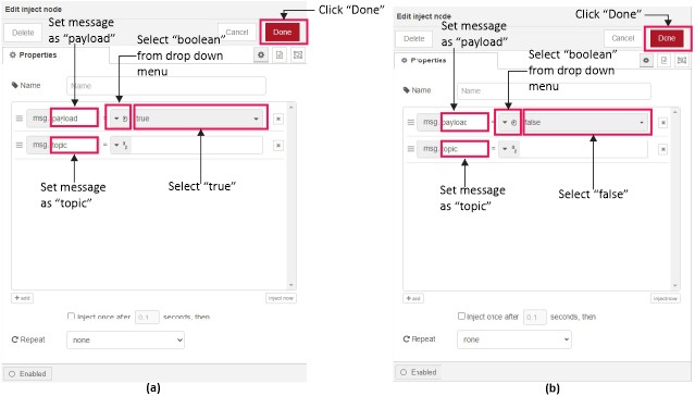
- Next double click on “debug” node then select “complete msg object” (Refer Figure 3(a) for node settings), Finally click “Done” button.
- Then double click on “ND8” node select “Channel-00” from the “Input” drop down menu and select I2C address from “Device address” (Refer Figure 3(b) for node settings), Finally click “Done” button.
*Refer MC-EX-ND8 Expansion Module enclosure for I2C address configuration. Then set I2C address by changing DIP switches on expansion module PCB. Remove enclosure for to access expansion module PCB.
OR
Use “I2C Scan” node for run I2C address scan

- For get information regarding “ND8” node click symbol then click on node selected (Check Figure 4).

- Link The nodes according to Figure 5, Click “deploy” button for run Node-Red program (Click on “true” state before feed input signal).

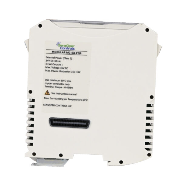 MC-EX-FQ4 | Transistor Output x 4