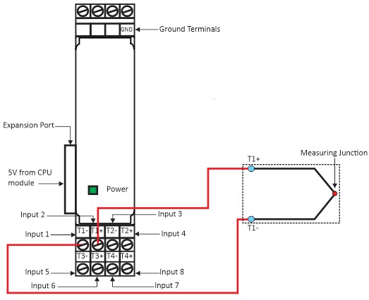
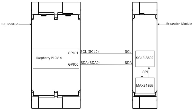
Wiring Diagram (Powerup & Thermocouple Input) Figure 1(a): Thermocouple Input Expansion module power up and Input wiring. CPU Module and Expansion Module GPIO Connection Diagram Figure 1(b): The GPIO connection with CPU module and Expansion Module. Doc navigationRun Example Program → Was this article helpful to you? Yes No How can we help? Name Email subject message