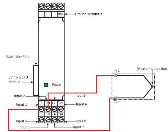
Figure 1 shows how to power up the Thermocouple Input Module. Module operation will voltage provide via CPU module. If the wiring is correctly done the Power indication LED will turn on. Further, this wiring diagram shows how to receive signal from Thermocouple.
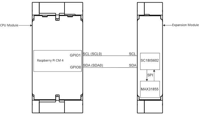
CPU Module and Expansion Module GPIO Connection Diagram
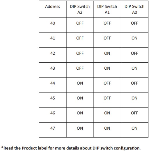
DIP Switch Configuration