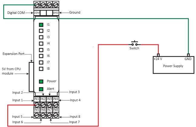
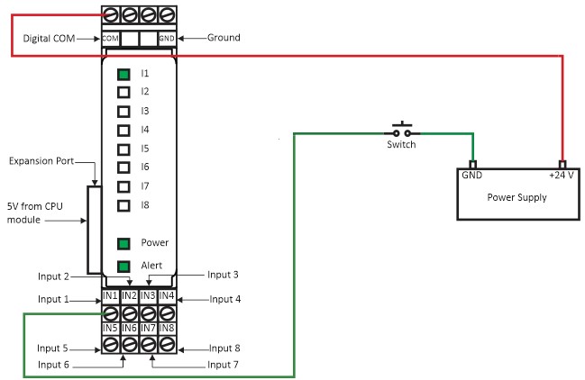
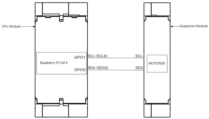
Wiring Diagram (Powerup & Input Terminals) Source Configuration Figure 1(a): Digital Input Expansion module power up and Input wiring (Source Configuration). Sink Configuration Figure 1(b): Digital Input Expansion module power up and Input wiring (Sink Configuration). *Make sure not turn on all DIP switches at same time. Figure 1(c): The GPIO connection with CPU module and Expansion Module. Doc navigationImplement and Deploy Node Red Program → Was this article helpful to you? Yes No How can we help? Name Email subject message