- After following Figure 1(a), (b), (c) diagram instructions in Wiring Diagram sections . Connect a Digital Input Expansion module in to the 40 pin
board to board connector in CPU Module (Explained in MC-CPU-CM4-Gx datasheet). - Now open Terminal Window after turn on the CPU Module.
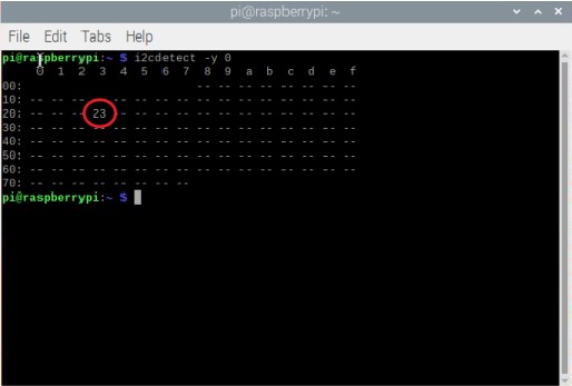
- Type ‘i2cdetect -y 0’ command and run the command.
- The result will be similar to the Figure 1 shown below.
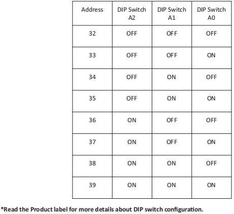
- Here the ‘0x23’ is the Digital Input expansion module I2C address, This I2c address can be changed according to user requirement
by changing the DIP switch configuration (Check Figure 1(a)) on expansion module.
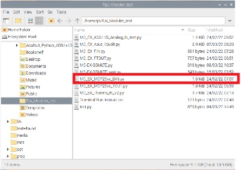
- Follow the File Manager > Pi > Rpi_Moduler_test, then open Rpi_Moduler_test folder.
- In Rpi_Moduler_test folder include example program for every expansion module.
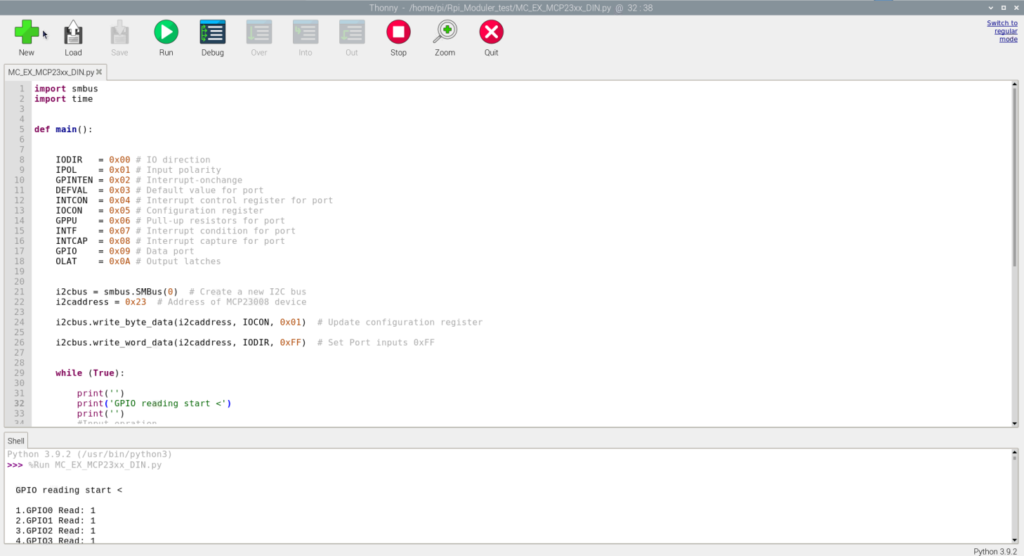
- Select the MC_EX_MC23xx_DIN.py example program that matches with the Digital Input expansion module shown in Figure 2.
9. The python program will open on default Thonny Python IDE. Click RUN for start the program shown in Figure 3.