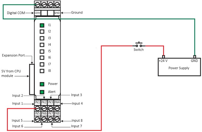
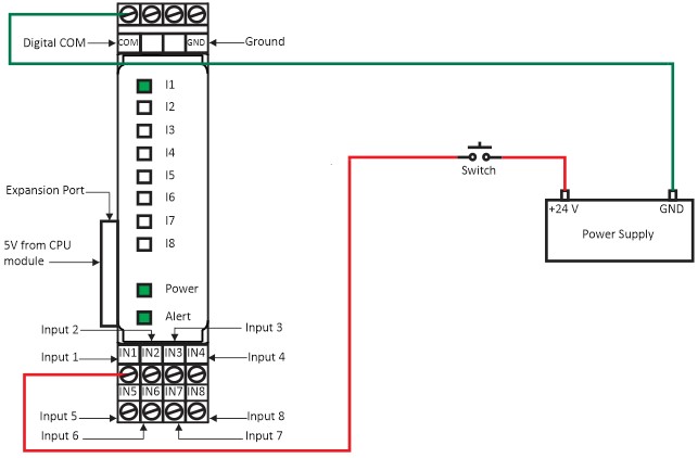
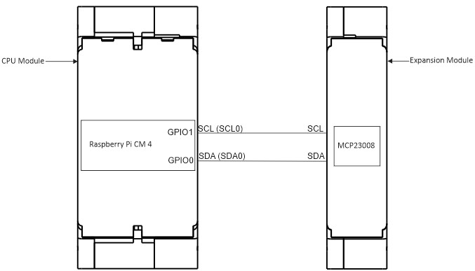
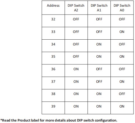
Wiring Diagram (Powerup & Input Terminals) Source Configuration Figure 1(a): The wiring diagram of the Digital Input Module (Source Configuration). Sink Configuration Figure 1(b): The wiring diagram of the Digital Input Module (Sink Configuration). CPU Module and Expansion Module GPIO Connection Diagram Figure 2: The GPIO connection with CPU module and Expansion Module. DIP Switch Configuration Figure 3: DIP Switch Configuration Address present in Decimal Doc navigation← Module Expansions Was this article helpful to you? Yes No How can we help? Name Email subject message