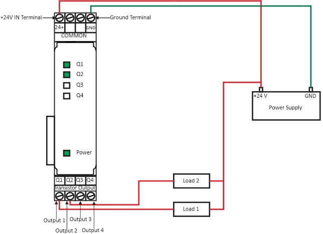
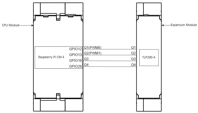
Wiring Diagram (Powerup & Output Terminals) Figure 1: Transistor Output Expansion module power up and output wiring. CPU Module and Expansion Module GPIO Connection Diagram Figure 2: The GPIO connection with CPU module and Expansion Module. OUTPUTGPIOQ1GPIO12Q2GPIO13Q3GPIO19Q4GPIO26Table 1: GPIO vs OUTPUT map. Doc navigationImplement and Deploy Node Red Program → Was this article helpful to you? Yes No How can we help? Name Email subject message