- Follow Wiring Diagram, complete wiring diagram.
- Follow Node-RED Startup Guide if you are beginner to run node red on these products.
- Open Node-RED Dashboard.
- Go to left “Toggle palette” & scroll down to “MC EX” category. Nodes in “MC EX” category nodes can use for program Modular industrial controller expansion modules (Check Figure 1).

- From “MC EX” category drag and drop “FQ4” node on Node-Red work space (Check Figure 2).

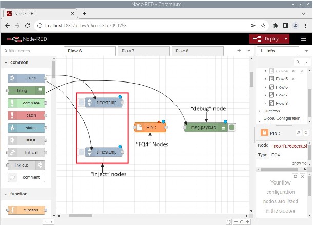
- Then scroll up to common category ,drag and drop two “inject” nodes & one “debug” nodes on Node-Red work space (Check Figure 3).
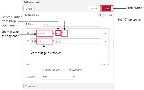
- Double click on one “inject” node, change the node settings according to Figure 4, Click “Done” button.
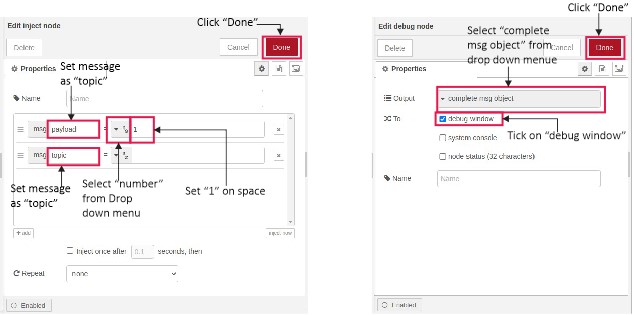
- Apply same process on other “inject” node, “debug” node (Follow Figure 5), Click “Done” button.
- Double click on “FQ4” node then select the input from drop down menu as shown in Figure 6, click “Done” button.

- For get information regarding “FQ4” node click “Book” symbol then click on node selected (Check Figure 7).

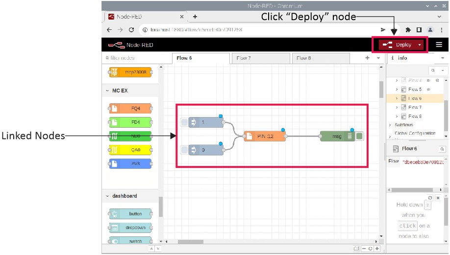
- Link The nodes according to Figure 8, Now click “Deploy” button for run Node-Red program.
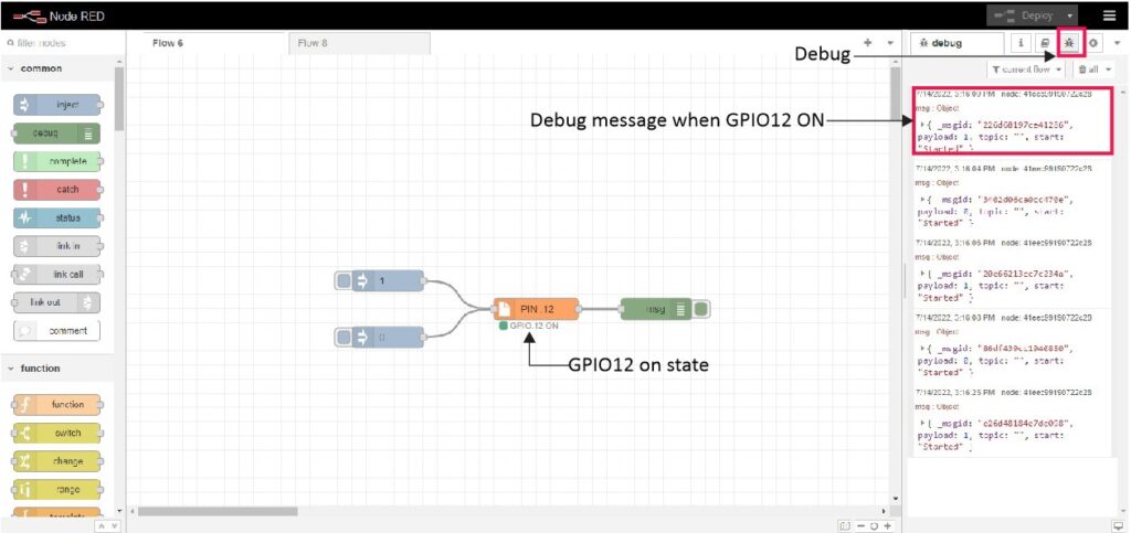
- For monitor Debug message click symbol, Figure 9(a) & (b) show the result when output “on” and “off” state .