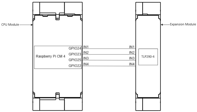
Pin Allocation Figure 1: The GPIO allocation with CPU module and Expansion Module. INPUTGPIOIN1GPIO24IN2GPIO23IN3GPIO25IN4GPIO22Table 1: GPIO Allocation. Doc navigation← DatasheetExpansion Module Node-Red Startup Guide → Was this article helpful to you? Yes No How can we help? Name Email subject message