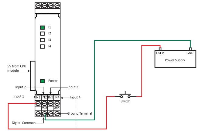
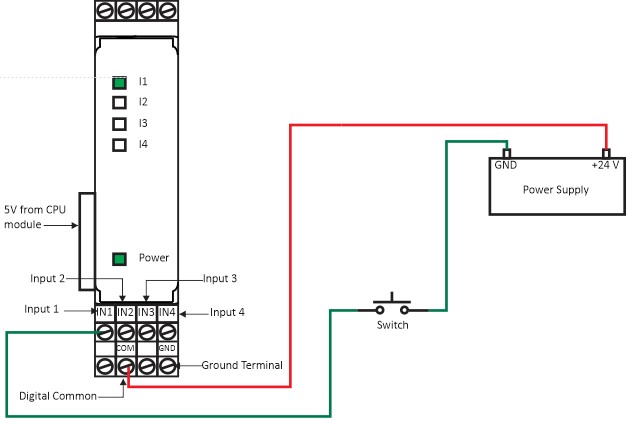
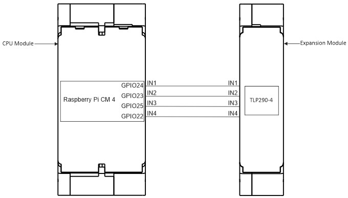
Wiring Diagram (Powerup & Input Terminals) Source Configuration Figure 1(a): Fast Input Expansion module power up and Input wiring (Source Configuration). Sink Configuration Figure 1(b): Fast Input Expansion module power up and Input wiring (Sink Configuration). CPU Module and Expansion Module GPIO Connection Diagram Figure 1(c): The GPIO connection with CPU module and Expansion Module. INPUTGPIOIN124IN223IN325IN422Table 1: GPIO vs INPUT map. Doc navigationRun Example Program → Was this article helpful to you? Yes No How can we help? Name Email subject message