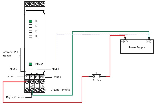
Source Configuration
Sink Configuration
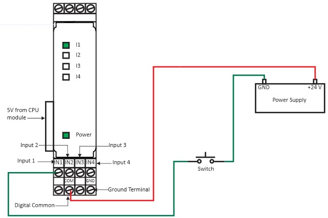
Figure 1(a), Figure 1(b) shows how to power up the Fast inputs Module. If the wiring is correctly done the Power indication LED will turn on. Further, this wiring diagram shows how to receive source or sink. When Input signal received the I1, I2, I3 & I4 LED indication will blink accordingly.
CPU Module and Expansion Module GPIO Connection Diagram
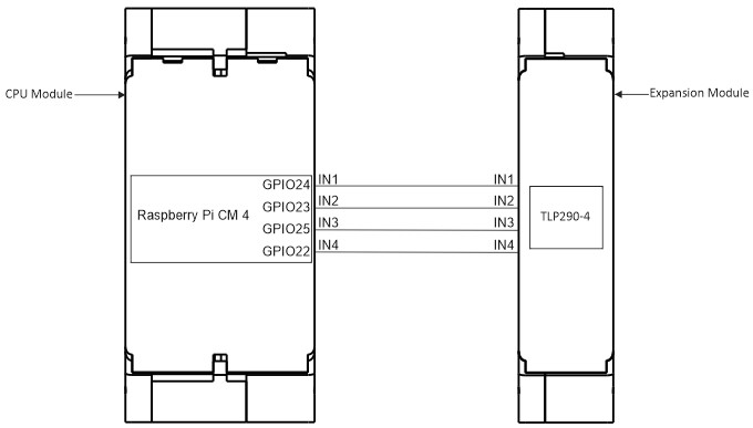
| INPUT | GPIO |
|---|---|
| IN1 | GPIO24 |
| IN2 | GPIO23 |
| IN3 | GPIO25 |
| IN4 | GPIO22 |