1. Home
  2. Docs
  3. MC-EX-AQ4 | Analog Output Expansion Module
  4. Datasheet
  5. Wiring Diagram (Powerup & Output Terminals)

Wiring Diagram (Powerup & Output Terminals)

Figure 1: The wiring diagram of the Analog Output Module.

Figure 1 shows how to power up the Module. Module operation will voltage provide via power supply. If the wiring is correctly done the Power indication LED will turn on.

CPU Module and Expansion Module GPIO Connection Diagram

Figure 2: The GPIO connection with CPU module and Expansion Module.

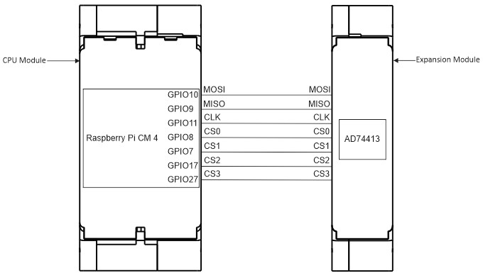
Chip Select Configuration

Figure 3: DIP Switch Arrangement for Chip select
Was this article helpful to you? Yes No

How can we help?