1. Home
  2. Docs
  3. MC-EX-AQ4 | Analog Output Expansion Module
  4. Expansion Module Startup Guide
  5. Wiring Diagram (Powerup & Output Terminals)

Wiring Diagram (Powerup & Output Terminals)

Figure 1(a): Analog Output Expansion module power up and output terminals wiring.

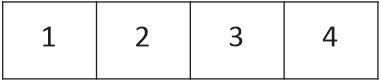
*Make sure not turn on all DIP switches at same time.

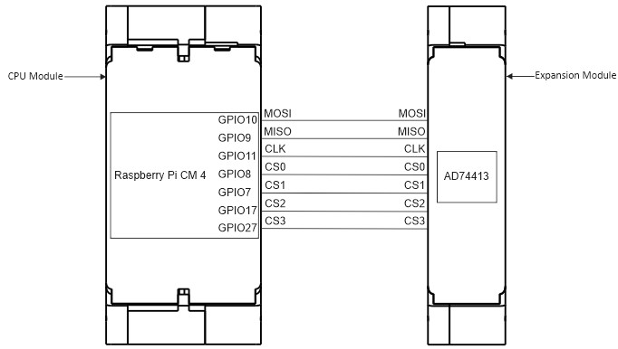
CPU Module and Expansion Module GPIO Connection Diagram

Figure 1(b): The GPIO connection with CPU module and Expansion Module.
Chip Selection GPIODIP Switch 1DIP Switch 2DIP Switch 3DIP Switch 4
GPIO 17OFFOFFOFFON
GPIO 27OFFOFFONOFF
GPIO 8OFFONOFFOFF
GPIO 7ONOFFOFFOFF
Table 1: Chip Select GPIO pins
Figure 1(C): DIP Switches Arrangement
Was this article helpful to you? Yes 1 No

How can we help?