- After following Figure 1(a),(b) diagram instructions in Wiring Diagram section. Connect a Analog Output Expansion module in to the 40 pin
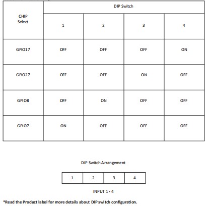
board to board connector in CPU Module (Explained in MC-CPU-CM4-Gx datasheet). - Change the DIP switches for select a chip according to Table 1 in Wiring Diagram section.
- Follow the File Manager > Pi > Rpi_Moduler_test path, then open Rpi_Moduler_test folder.
- In Rpi_Moduler_test folder include example program for every expansion module.
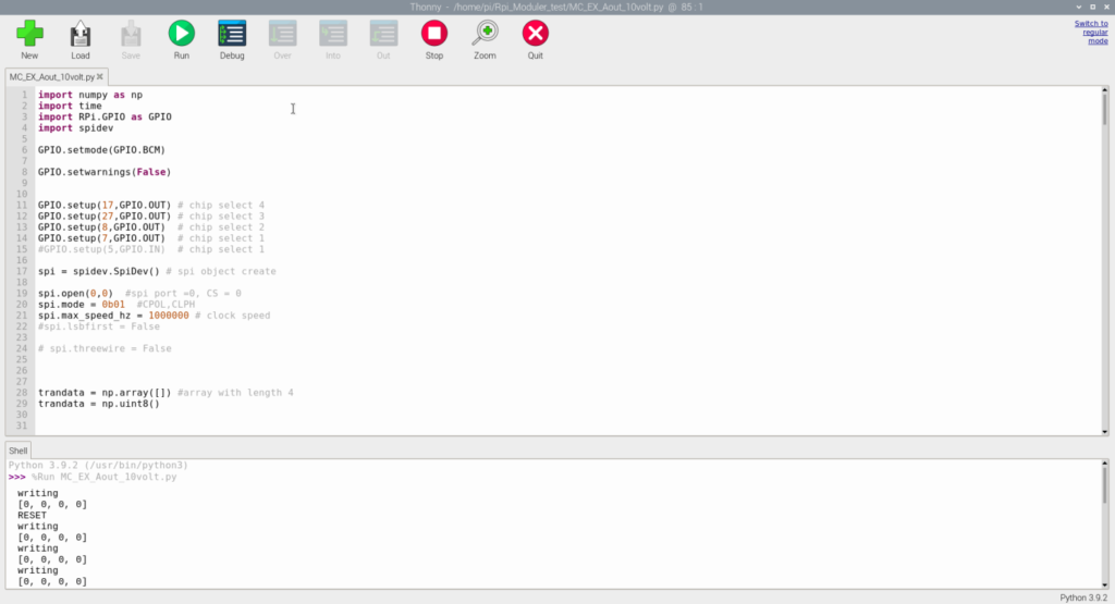
- Select the MC_EX_Aout_10volt.py example program that matches with the Analog Outputs expansion module shown in Figure 1.

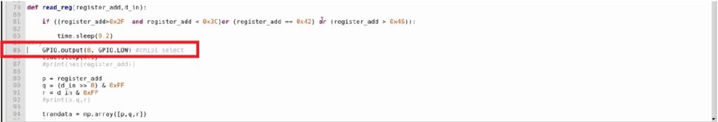
- Change the GPIO pin number in MC_EX_Aout_10volt.py file line 85 according to selected chip according to Figure 2(a), (b) shows below
(Refer Table 1 Wiring Diagram section for get GPIO pin number).
7. The python program will open on default Thonny Python IDE. Click RUN for start the program shown in Figure 3.