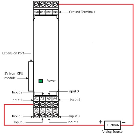
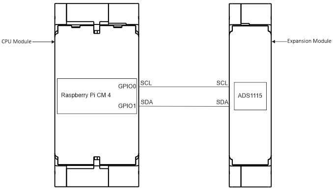
Wiring Diagram (Power & Input Terminals) Figure1(b) :The wiring diagram of the Analog Input Module *Make sure not turn on all DIP switches at same time. CPU Module and Expansion Module GPIO Connection Diagram Figure 1(b): The GPIO connection with CPU module and Expansion Module. Doc navigationRun Example Program → Was this article helpful to you? Yes No How can we help? Name Email subject message