Flashing OS to the eMMC
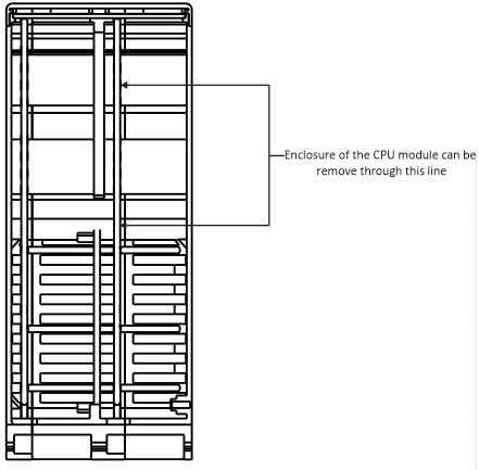
*First the enclosure of the CPU module should remove the mini jumper should connect with eMMC mode pin. This connection disables the CPU modules to eMMC boot mode.
For Windows User,
Under Windows, an installer is available to install the required drivers and boot tool automatically. Alternatively, a user can compile and run it using Cygwin and/or install the drivers manually.
- Now download and run rpiboot_setup.exe Windows installer to install the drivers and boot tool into PC (Please ensure you are not
writing to any USB devices whilst the installer is running.). - Connect the CPU Module to your host PC via USB cable.
- Apply power to the CPU Module; Windows should now find the hardware and install the driver.
- Once the driver installation is complete, run the rpiboot_setup.exe tool that was previously installed to PC.
- After a few seconds, the Compute Module eMMC will pop up under Windows as a disk (USB mass storage device).
- Now format the eMMC storage such like SD Card Formatter (Make sure and note the drive letter).
- Now download and install Raspberry Pi Imager tool in to PC (Also you can use tool like Win32DiskImager).
- Click CHOOSE OS and select Raspberry PI OS (32-bit) version .
- Then click CHOOSE STORAGE and select correct storage drive letter.
- Now click WRITE for write image to eMMC.
- After write completed open the eMMC storage drive and open config.txt file replace the code lines in below Config.txt content after clear existing code
lines and save the file.
Note: If you download Raspberry Pi OS Image from our web site, no need to do changes in config.txt file.
For more details and install Linux user follow this link .
- After the config.txt file changes completed remove the jumper that was earlier connected for eMMC boot disable.
- Now you can boot the CPU module and use normally.
Config.txt content
# For more options and information see
# http://rpf.io/configtxt
# Some settings may impact device functionality. See link above for details
# uncomment if you get no picture on HDMI for a default “safe” mode
#hdmi_safe=1
# uncomment this if your display has a black border of unused pixels visible
# and your display can output without overscan
disable_overscan=1
# uncomment the following to adjust overscan. Use positive numbers if console
# goes off screen, and negative if there is too much border
#overscan_left=16
#overscan_right=16
#overscan_top=16
#overscan_bottom=16
# uncomment to force a console size. By default it will be display’s size minus
# overscan.
#framebuffer_width=1280
dtoverlay=i2c-rtc,ds3231,i2c_csi_dsi #framebuffer_height=720
# uncomment if hdmi display is not detected and composite is being output
#hdmi_force_hotplug=1
# uncomment to force a specific HDMI mode (this will force VGA)
hdmi_group=0
#hdmi_mode=4
# uncomment to force a HDMI mode rather than DVI. This can make audio work in
# DMT (computer monitor) modes
hdmi_drive=2
# uncomment to increase signal to HDMI, if you have interference, blanking, or
# no display
config_hdmi_boost=4
# uncomment for composite PAL
#sdtv_mode=2
#uncomment to overclock the arm. 700 MHz is the default.
#arm_freq=800
# Uncomment some or all of these to enable the optional hardware interfaces
dtparam=i2c_arm=on
#dtparam=i2s=on
dtparam=spi=on
# Uncomment this to enable infrared communication.
#dtoverlay=gpio-ir,gpio_pin=17
#dtoverlay=gpio-ir-tx,gpio_pin=18
# Additional overlays and parameters are documented /boot/overlays/README
# Enable audio (loads snd_bcm2835)
dtparam=audio=on
[pi4]
# Enable DRM VC4 V3D driver on top of the dispmanx display stack
dtoverlay=vc4-fkms-v3d
max_framebuffers=2
[all]
#dtoverlay=vc4-fkms-v3d
dtoverlay=dwc2,dr_mode=host
dtoverlay=gpio-no-irq
dtparam=i2c_vc=on
dtoverlay=i2c-rtc,pcf85063a,i2c_csi_dsi
dtparam=i2c=on
dtparam=i2c_arm_baudrate=400000
enable_uart=1
dtoverlay=i2c-rtc,ds3231
dtoverlay=disable-bt
enable_uart=1