Figure 1 shows how to power up the Transistor Output Module. If the wiring is correctly done the Power indication LED will turn on. Further, this wiring diagram shows how to send signal to load. When Output signal begin the Q1, Q2, Q3, Q4, Q5, Q6, Q7 & Q8 LED indication will blink accordingly. The Alert indication LED will blink according to functional state.
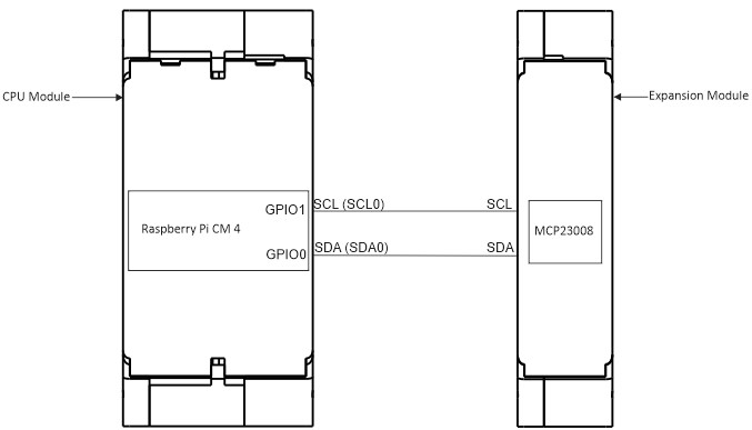
CPU Module and Expansion Module GPIO Connection Diagram
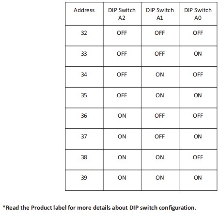
DIP Switch Configuration